| .. | ||
| n_channel_h-bridge_motorcontrol.png | ||
| Readme.md | ||
🔌 N-Channel MOSFET: Overview
An N-channel MOSFET (Metal-Oxide-Semiconductor Field-Effect Transistor) is a type of transistor that controls current flow using an electric field — it's a three-terminal device with:
- Gate (G) — controls the transistor
- Drain (D) — where current flows into
- Source (S) — where current flows out of
When a positive voltage is applied to the gate relative to the source, the MOSFET turns on, allowing current to flow from drain to source (D → S).
⚙️ Common Uses
- Power switching in motor drivers
- Voltage regulation
- Signal modulation
- Digital logic switching
🔁 Use in an H-Bridge Motor Controller
An H-bridge is a circuit used to control the direction of a DC motor. It consists of four switches, typically implemented with N-channel MOSFETs:
H-Bridge Configuration:
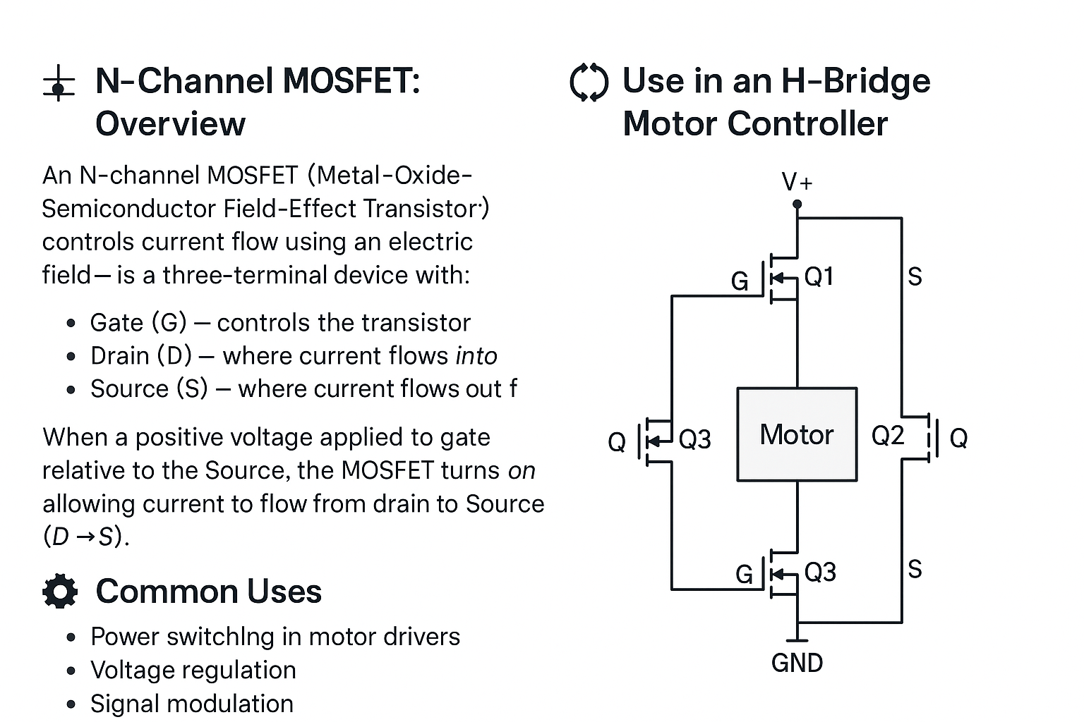
- Q1 + Q4 ON → motor spins in one direction
- Q2 + Q3 ON → motor spins in the opposite direction
- PWM control on low-side N-MOSFETs allows speed control
Because N-channel MOSFETs conduct easily when their gate voltage is higher than the source, they're ideal for low-side switching. High-side use may require gate driver circuits to boost voltage.
🔥 Difference Between P-Channel and N-Channel MOSFETs
MOSFETs (Metal-Oxide-Semiconductor Field-Effect Transistors) are used to switch and amplify electronic signals.
There are two main types: N-Channel and P-Channel.
Each has different behaviors and is suited to different roles in circuits.
🧲 N-Channel MOSFET
🔍 Characteristics:
- Current flows from Drain to Source when turned ON.
- Turns ON when the Gate voltage (Vgs) is positive relative to the Source.
- Lower ON-resistance (better conductivity) compared to P-Channel for the same size.
- Preferred for switching low-side (between load and ground).
✅ Strengths:
- Higher efficiency
- Faster switching
- Lower cost (per performance level)
❌ Weaknesses:
- Usually requires extra circuitry (like level shifters) when used for high-side switching (above the load).
🧠 Common Uses:
- Low-side switches
- Buck converters
- Motor controllers (low-side drivers)
🧲 P-Channel MOSFET
🔍 Characteristics:
- Current flows from Source to Drain when turned ON.
- Turns ON when the Gate voltage (Vgs) is negative relative to the Source.
- Typically higher ON-resistance and slower compared to N-Channel MOSFETs.
- Preferred for switching high-side (between power source and load).
✅ Strengths:
- Simplifies high-side switching (easy to control with low voltages)
- Useful when you need to disconnect the positive voltage rail.
❌ Weaknesses:
- Less efficient (higher resistance)
- Larger physical size for the same current handling compared to N-Channel.
🧠 Common Uses:
- High-side switches
- Power management circuits
- Battery protection circuits
⚡ Quick Comparison Table
| Feature | N-Channel | P-Channel |
|---|---|---|
| Current Direction | Drain → Source | Source → Drain |
| Turn-On Condition (Vgs) | Positive | Negative |
| Efficiency | Higher | Lower |
| Typical Placement | Low-side (GND side) switching | High-side (VCC side) switching |
| Complexity for High-Side | Needs extra circuitry (bootstrap) | Simple control |
🎯 Final Thoughts
- Use N-Channel when you want higher efficiency and lower cost, especially on the low side.
- Use P-Channel when you need a simple high-side switch without complicated control circuitry.
- In many advanced designs, engineers prefer two N-Channel MOSFETs (with extra drivers) even for high-side switching to maximize efficiency.
Choosing the right type depends on your circuit's needs! 🚀