| .. | ||
| active_components_symbols.png | ||
| n_channel_h-bridge_motorcontrol.png | ||
| passive_components_symbols.png | ||
| Readme.md | ||
Difference Between Active and Passive Components in Electronics
🔋 Active Components
Active components are electronic devices that can amplify signals, control current, or produce energy. They require an external power source to function.
Examples:
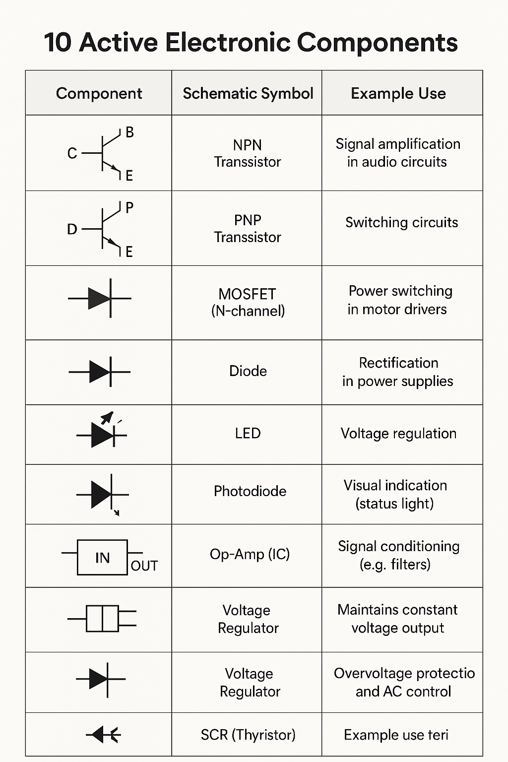
- Transistors – Amplify or switch electronic signals
- Diodes (including LEDs) – Allow current in one direction, used in rectification
- Integrated Circuits (ICs) – Contain multiple active and passive components
Key Features:
- Require external power to operate
- Can inject power into a circuit
- Can control the flow of electricity
- Used for amplification, signal processing, and switching
🔌 Passive Components
Passive components cannot amplify or generate power. They only respond to the electrical signals applied to them.
Examples:
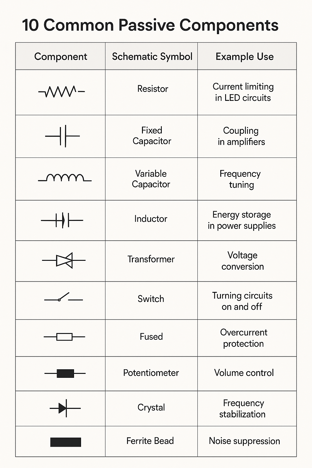
- Resistors – Limit current flow
- Capacitors – Store and release energy as an electric field
- Inductors – Store energy in a magnetic field
- Transformers – Transfer energy between circuits via magnetic fields
Key Features:
- Do not require external power to operate
- Cannot amplify signals
- Used for filtering, energy storage, tuning, and impedance matching
⚖️ Quick Analogy
- Passive Component: Like a valve or container — it regulates or stores energy.
- Active Component: Like a pump — it can add energy and control the system dynamically.
🔋 10 Active Electronic Components
🔌 10 Passive Electronic Components
🔌 N-Channel MOSFET: Overview
An N-channel MOSFET (Metal-Oxide-Semiconductor Field-Effect Transistor) is a type of transistor that controls current flow using an electric field — it's a three-terminal device with:
- Gate (G) — controls the transistor
- Drain (D) — where current flows into
- Source (S) — where current flows out of
When a positive voltage is applied to the gate relative to the source, the MOSFET turns on, allowing current to flow from drain to source (D → S).
⚙️ Common Uses
- Power switching in motor drivers
- Voltage regulation
- Signal modulation
- Digital logic switching
🔁 Use in an H-Bridge Motor Controller
An H-bridge is a circuit used to control the direction of a DC motor. It consists of four switches, typically implemented with N-channel MOSFETs:
H-Bridge Configuration:
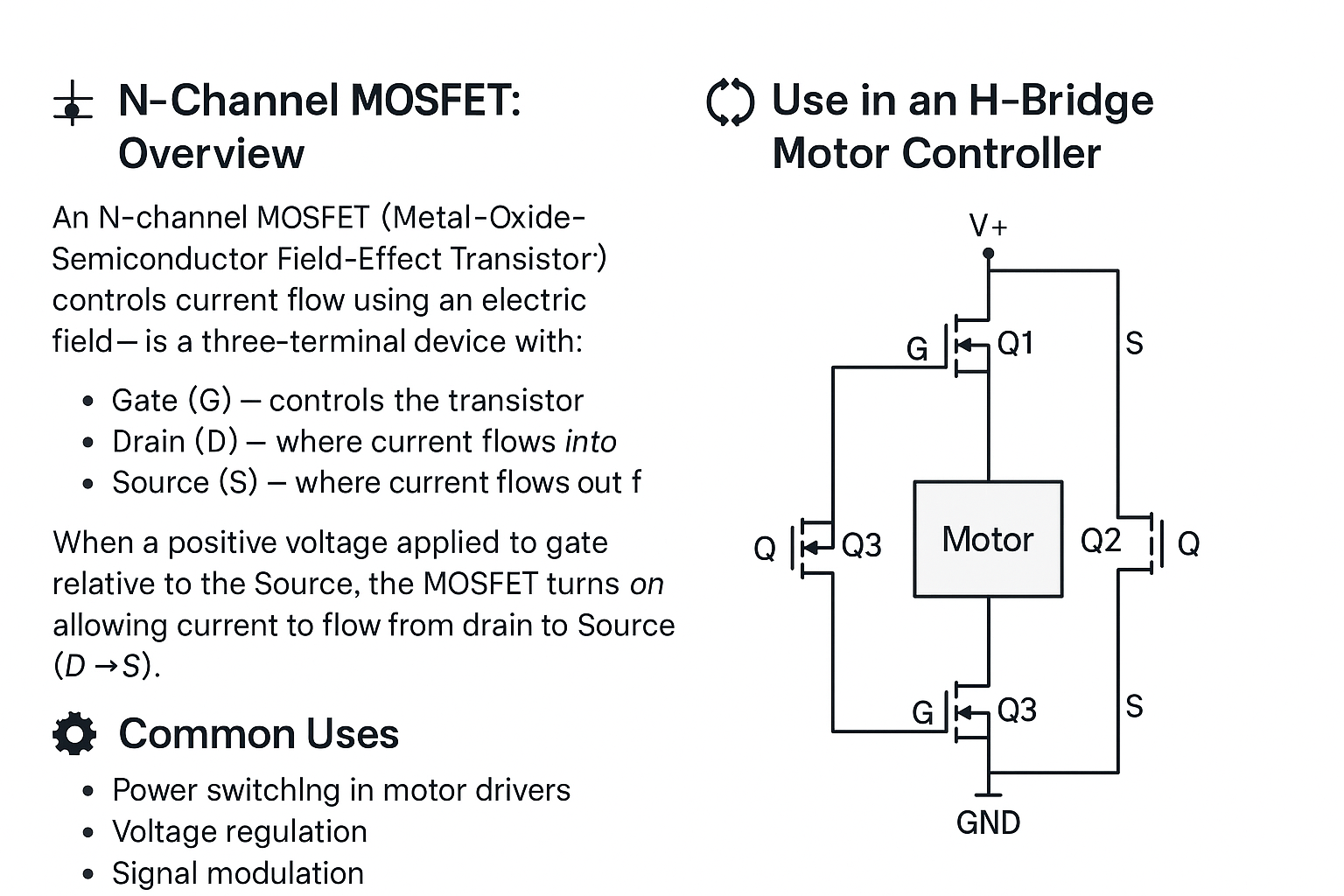
- Q1 + Q4 ON → motor spins in one direction
- Q2 + Q3 ON → motor spins in the opposite direction
- PWM control on low-side N-MOSFETs allows speed control
Because N-channel MOSFETs conduct easily when their gate voltage is higher than the source, they're ideal for low-side switching. High-side use may require gate driver circuits to boost voltage.
