| .. | ||
| n_channel_h-bridge_motorcontrol.png | ||
| Readme.md | ||
🔌 N-Channel MOSFET: Overview
An N-channel MOSFET (Metal-Oxide-Semiconductor Field-Effect Transistor) is a type of transistor that controls current flow using an electric field — it's a three-terminal device with:
- Gate (G) — controls the transistor
- Drain (D) — where current flows into
- Source (S) — where current flows out of
When a positive voltage is applied to the gate relative to the source, the MOSFET turns on, allowing current to flow from drain to source (D → S).
⚙️ Common Uses
- Power switching in motor drivers
- Voltage regulation
- Signal modulation
- Digital logic switching
🔁 Use in an H-Bridge Motor Controller
An H-bridge is a circuit used to control the direction of a DC motor. It consists of four switches, typically implemented with N-channel MOSFETs:
H-Bridge Configuration:
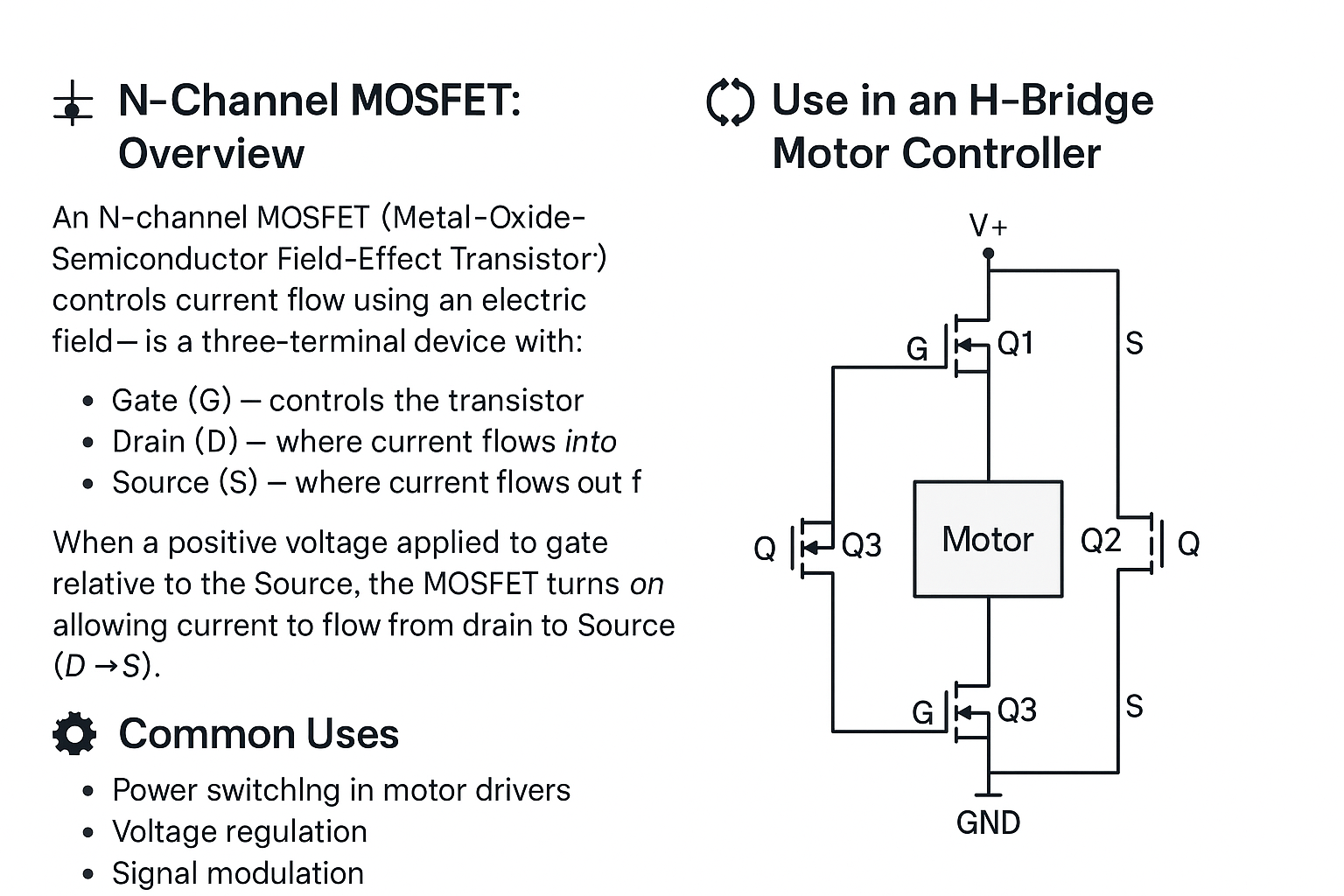
- Q1 + Q4 ON → motor spins in one direction
- Q2 + Q3 ON → motor spins in the opposite direction
- PWM control on low-side N-MOSFETs allows speed control
Because N-channel MOSFETs conduct easily when their gate voltage is higher than the source, they're ideal for low-side switching. High-side use may require gate driver circuits to boost voltage.