3.5 KiB
3.5 KiB
Difference Between Active and Passive Components in Electronics
🔋 Active Components
Active components are electronic devices that can amplify signals, control current, or produce energy. They require an external power source to function.
Examples:
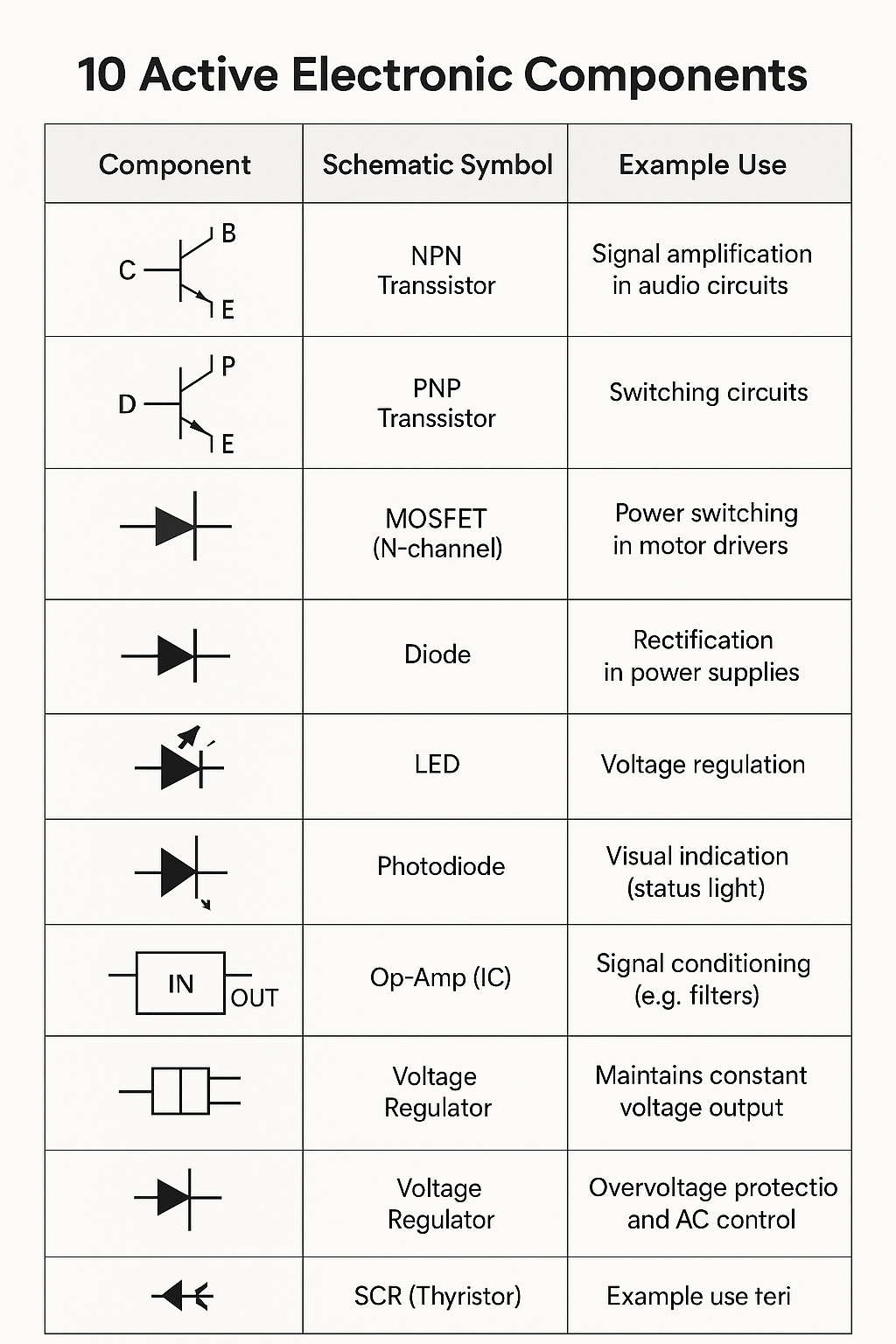
- Transistors – Amplify or switch electronic signals
- Diodes (including LEDs) – Allow current in one direction, used in rectification
- Integrated Circuits (ICs) – Contain multiple active and passive components
Key Features:
- Require external power to operate
- Can inject power into a circuit
- Can control the flow of electricity
- Used for amplification, signal processing, and switching
🔌 Passive Components
Passive components cannot amplify or generate power. They only respond to the electrical signals applied to them.
Examples:
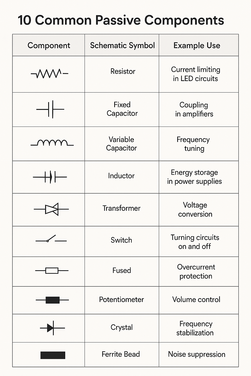
- Resistors – Limit current flow
- Capacitors – Store and release energy as an electric field
- Inductors – Store energy in a magnetic field
- Transformers – Transfer energy between circuits via magnetic fields
Key Features:
- Do not require external power to operate
- Cannot amplify signals
- Used for filtering, energy storage, tuning, and impedance matching
⚖️ Quick Analogy
- Passive Component: Like a valve or container — it regulates or stores energy.
- Active Component: Like a pump — it can add energy and control the system dynamically.
🔋 10 Active Electronic Components
🔌 10 Passive Electronic Components
🔁 Use in a Timer Circuit
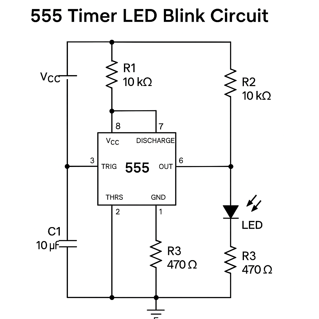
🔧 555 Timer LED Blinker Circuit (Astable Mode)
This project uses a 555 timer IC in astable mode to blink an LED on and off at a regular interval.
🧰 Required Components
| Component | Value | Quantity |
|---|---|---|
| 555 Timer IC | NE555 | 1 |
| Resistor R1 | 10 kΩ | 1 |
| Resistor R2 | 10 kΩ | 1 |
| Resistor R3 | 470 Ω | 1 |
| Capacitor C1 | 10 µF (electrolytic) | 1 |
| LED | Any color | 1 |
| Power Supply | 5V – 9V DC | 1 |
| Breadboard + jumper wires | — | — |
🔁 How It Works
The 555 timer is configured in astable mode, which means it continuously switches between high and low states:
- The output pin (pin 3) alternates between HIGH and LOW.
- This causes the LED to blink on and off.
- The timing interval is determined by R1, R2, and C1.
⏱️ Blinking Frequency Formula
To change the blink rate:
T = 0.693 × (R1 + 2×R2) × C1
Where:
Tis the period in secondsR1,R2in ohmsC1in farads
🔌 Circuit Schematic
✅ Assembly Tips
- Ensure pin 1 is connected to GND
- Pin 8 goes to Vcc
- Make sure the capacitor polarity is correct (− side to GND)
- Use a current-limiting resistor (R3) with the LED to prevent damage
This is a perfect beginner project to understand timers, oscillation, and basic LED control. Let me know if you'd like to simulate this or turn it into a PCB design!